 Block series OF-W
Multiconductor Shield (Copper Tape)
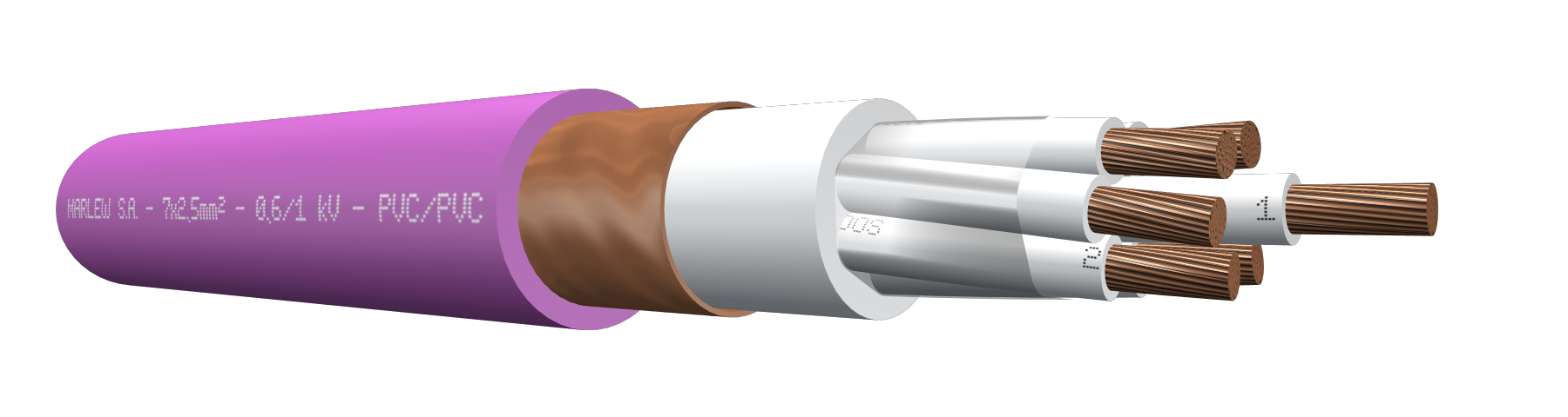


Copper tape shield
Control, signalling, measuring and protective equipment; electric controls of industrial installations. Installed in aerial trays, gutters or conduits, buried in ducts or directly buried. It provides additional electromagnetic protection.
Features
Temperature ratings: 75ºC (operating), 160°C (short circuit)
Voltage rating: 600/1000 Volt A.C. – 1200 Volt A.C. (Max) – 1500 Volt D.C.
Construction requirements: IRAM 2178-1 – IEC 60502-1
Conductor requirements: IRAM NM 280 – IEC 60228
Conductor: Annealed electrolytic copper - Flexible stranding class 5
Insulation: PVC
Shield: Helical copper tape with 100% coverage and adequate overlap
Sheath: Flame retardant PVC
Fire requirements: As per IEC 60332-3-24

Electromagnetic interference protection

Fire-retardant

Flexible stranded conductors
Sequentially marked

Industrial applications

Tray cable
Identification
| Standard | ||
|---|---|---|
| Sheath | Conductors | |
| Multiconductor |  |  alphanumeric identification alphanumeric identification |
Instalation


Constructive variants
The information provided corresponds to the standard version, and different alternatives of insulation and / or covering can be used upon request.
ELECTRICAL CHARACTERISTICS
Resistances and intensity of admissible currents
| Nominal cross-section sq mm² | Electrical resistance at 20ºC in C.C Ohm/km | Electrical resistance at 90ºC in C.A. Ohm/km | Current-carrying capacity in free air. At 40°C as per IEC 364-5-523. Formations in perforated trays or ladder type. (Ampere) | ||||||
|---|---|---|---|---|---|---|---|---|---|
| 2x | 4x | 7x | 10x | 19x | 30x | 48x | |||
| 1 | 19.5 | 23.3 | -- | -- | -- | -- | -- | -- | -- |
| 1.5 | 13.3 | 15.9 | 18.1 | 15.3 | 12.7 | 9.1 | 9.1 | 8.1 | 6.3 |
| 2.5 | 7.98 | 9.55 | 25 | 21 | 17.5 | 12.5 | 12.5 | 11.3 | 8.8 |
| 4 | 4.95 | 5.92 | 33 | 29 | 23.1 | 16.5 | 16.5 | 14.9 | -- |
As from seven-conductors, we’ve additionally applied the correction factor for more than three conductors the chart 310.15 (B)(3)(a) of the NFPA70.
DIMENSIONS & WEIGHT
| Cable Formation N° Cond. x cross-section (mm²) | Diameter below shield mm | External diameter mm | Weight kg/km | Code |
|---|---|---|---|---|
| 5x1 | 9.6 | 13.0 | 246 | OF 0510 W |
| 7x1 | 10.4 | 13.7 | 280 | OF 0710 W |
| 10x1 | 12.3 | 15.7 | 352 | OF 1010 W |
| 12x1 | 13.3 | 16.6 | 397 | OF 1210 W |
| 14x1 | 14.2 | 17.5 | 441 | OF 1410 W |
| 19x1 | 16.2 | 19.5 | 546 | OF 1910 W |
| 24x1 | 17.9 | 21.3 | 648 | OF 2410 W |
| 30x1 | 19.8 | 23.2 | 782 | OF 3010 W |
| 37x1 | 21.8 | 25.2 | 920 | OF 3710 W |
| 48x1 | 24.5 | 27.9 | 1131 | OF 4810 W |
| 3x1.5 | 9.0 | 12.4 | 227 | OF 0315 W |
| 4x1.5 | 9.4 | 12.8 | 247 | OF 0415 W |
| 5x1.5 | 10.3 | 13.6 | 276 | OF 0515 W |
| 7x1.5 | 11.2 | 14.5 | 327 | OF 0715 W |
| 10x1.5 | 13.3 | 16.6 | 413 | OF 1015 W |
| 12x1.5 | 14.4 | 17.7 | 469 | OF 1215 W |
| 14x1.5 | 15.3 | 18.7 | 524 | OF 1415 W |
| 19x1.5 | 17.5 | 20.8 | 656 | OF 1915 W |
| 24x1.5 | 19.4 | 22.8 | 799 | OF 2415 W |
| 30x1.5 | 21.5 | 24.9 | 951 | OF 3015 W |
| 37x1.5 | 23.6 | 27.0 | 1126 | OF 3715 W |
| 48x1.5 | 27.0 | 30.6 | 1436 | OF 4815 W |
| 2x2.5 | 9.0 | 12.4 | 231 | OF 0225 W |
| 3x2.5 | 9.6 | 13.0 | 263 | OF 0325 W |
| 4x2.5 | 10.5 | 13.8 | 298 | OF 0425 W |
| 5x2.5 | 11.5 | 14.8 | 347 | OF 0525 W |
| 7x2.5 | 12.5 | 15.8 | 418 | OF 0725 W |
| 10x2.5 | 14.9 | 18.2 | 531 | OF 1025 W |
| 12x2.5 | 16.1 | 19.4 | 608 | OF 1225 W |
| 14x2.5 | 17.2 | 20.5 | 684 | OF 1425 W |
| 19x2.5 | 19.7 | 23.1 | 883 | OF 1925 W |
| 24x2.5 | 21.9 | 25.3 | 1064 | OF 2425 W |
| 30x2.5 | 24.2 | 27.6 | 1278 | OF 3025 W |
| 37x2.5 | 26.7 | 30.3 | 1537 | OF 3725 W |
| 48x2.5 | 30.5 | 34.3 | 1966 | OF 4825 W |
| 2x4 | 10.9 | 14.2 | 305 | OF 0240 W |
| 3x4 | 11.6 | 14.9 | 354 | OF 0340 W |
| 4x4 | 12.7 | 16.0 | 417 | OF 0440 W |
| 5x4 | 14.0 | 17.3 | 491 | OF 0540 W |
| 7x4 | 15.3 | 18.6 | 600 | OF 0740 W |
| 10x4 | 18.3 | 21.6 | 763 | OF 1040 W |
| 12x4 | 19.8 | 23.2 | 896 | OF 1240 W |
| 14x4 | 21.2 | 24.6 | 1013 | OF 1440 W |
| 19x4 | 24.4 | 27.8 | 1302 | OF 1940 W |
| 24x4 | 27.5 | 31.1 | 1629 | OF 2440 W |
| 30x4 | 30.5 | 34.3 | 1980 | OF 3040 W |
| 37x4 | 33.6 | 37.6 | 2388 | OF 3740 W |