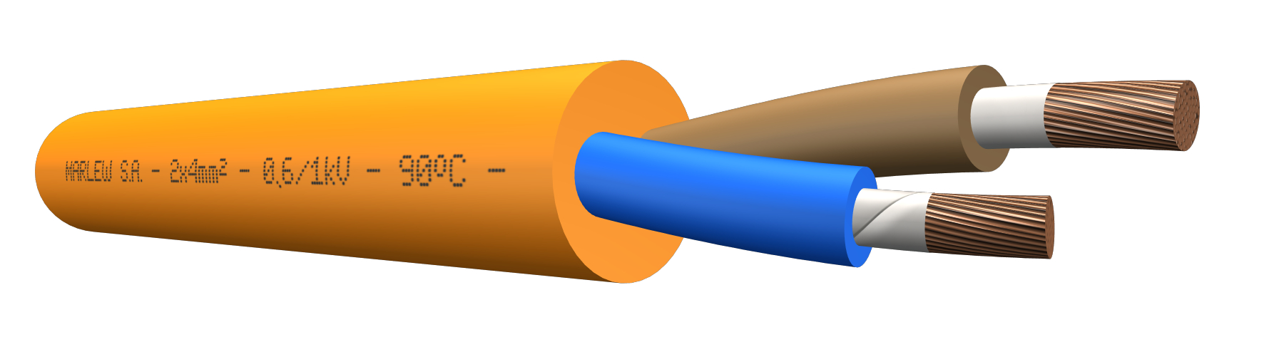
 series RP
Single-conductor up to four-conductor


For fixed power distribution networks for alternating current (50/60Hz), for single-phase systems (220/110V), three-phase systems (380/190V) and systems with voltages up to 1kV. For Direct Current, used in systems with voltages up to 1.5kV Use in closed environments with a high concentration of people (airports, hospitals, trains, cinemas, shopping centers, tunnels) and in control rooms with electronic equipment sensitive to the exposure of corrosive gases. Installed in conduits, trays, cable ladders, in direct open air or indoors, buried in a trench or in ducts.
Features
Temperature ratings: 90°C (Operating) – 130°C (Overload) – 250°C (Short-Circuit)
Voltage rating: 600/1000 Volt A.C. – 1200 Volt A.C. (Max) – 1500 Volt D.C.
Construction requirements: IRAM 62266 – IEC 60502-1
Conductor requirements: IRAM NM 280 – IEC 60228
Conductor: Annealed electrolytic copper - Flexible stranding class 5
Insulation: Mica tape + XLPE (Cross-Linked Polyethylene)
Sheath: LSZH-HFFR (Low Smoke Zero Halogen - Halogen Free Flame Retardant), flame retardant, sunlight, and oil resistant
Fire requirements: As per IEC 60332-3-24
Fire resistance standards: As per IEC 60331-21 (70000 BTU-750°C applied for 90 minutes)
Standard for Halogen absence and corrosive gases: IEC 60754-1/2
Smoke transparency requirements: IEC 61034-1/2
Toxicity standard: NES 713 – CEI 20.37
Oils requirements: As per ICEA S 73-532
Outdoors requirements: As per UL 2556 (UV rays)
Water behaviour requirements: Suitable for AD7 (Occasional water submersion)

Fire-retardant

Fire-resistant

Halogen free

Low smoke

Mineral oil resistant

UV resistant
Identification
| Standard | ||
|---|---|---|
| Sheath | Conductors | |
| 1 Conductor |  |  |
| 2 Conductors | |  |
| 3 Conductors | |   |
| 4 Conductors | | |
Instalation


Constructive variants
The information provided corresponds to the standard version. Special design can be manufactured to comply with reinforced circuit integrity, complying with other standards such as IEC 60331-1/2, EN 50200 or BS 6387.
ELECTRICAL CHARACTERISTICS
Resistances, reactance and intensity of admissible currents
| Nominal cross-section (mm²) | Electrical resistance in D.C. at 20°C (Ohm/km) | Electrical resistance in C.C. at 90°C (Ohm/km) | Inductive reactance at 50Hz (Ohm/Km) | ||||
|---|---|---|---|---|---|---|---|
| 1 Conductor (1) | 1 Conductor (2) | 1 Conductor (3) | Multiconductor (4) | 4 Conductors (5) | |||
 |  |  |  |  | |||
| 1 | 19.5 | 24.86 | 0.173 | 0.216 | 0.158 | 0.119 | 0.126 |
| 1.5 | 13.3 | 16.96 | 0.162 | 0.206 | 0.148 | 0.111 | 0.118 |
| 2.5 | 7.98 | 10.18 | 0.151 | 0.194 | 0.136 | 0.103 | 0.110 |
| 4 | 4.95 | 6.31 | 0.142 | 0.186 | 0.128 | 0.097 | 0.105 |
| 6 | 3.3 | 4.21 | 0.133 | 0.176 | 0.118 | 0.090 | 0.098 |
| 10 | 1.91 | 2.44 | 0.122 | 0.166 | 0.107 | 0.084 | 0.091 |
| 16 | 1.21 | 1.54 | 0.117 | 0.160 | 0.102 | 0.082 | 0.089 |
| 25 | 0.78 | 0.99 | 0.112 | 0.155 | 0.097 | 0.079 | 0.087 |
| 35 | 0.554 | 0.707 | 0.108 | 0.151 | 0.093 | 0.077 | 0.084 |
| 50 | 0.386 | 0.493 | 0.105 | 0.148 | 0.090 | 0.076 | 0.083 |
| 70 | 0.272 | 0.348 | 0.101 | 0.144 | 0.086 | 0.074 | 0.082 |
| 95 | 0.206 | 0.264 | 0.098 | 0.141 | 0.083 | 0.072 | 0.079 |
| 120 | 0.161 | 0.207 | 0.097 | 0.140 | 0.082 | 0.072 | 0.079 |
| 150 | 0.129 | 0.167 | 0.095 | 0.139 | 0.081 | 0.071 | 0.079 |
| 185 | 0.106 | 0.138 | 0.095 | 0.138 | 0.080 | 0.072 | 0.079 |
| 240 | 0.0801 | 0.106 | 0.093 | 0.137 | 0.079 | 0.071 | 0.078 |
| 300 | 0.0641 | 0.0860 | 0.092 | 0.136 | 0.078 | 0.070 | 0.077 |
| 400 | 0.0486 | 0.0675 | 0.091 | 0.135 | 0.076 | -- | -- |
| 500 | 0.0384 | 0.0557 | 0.090 | 0.134 | 0.076 | -- | -- |
| 630 | 0.0287 | 0.0451 | 0.086 | 0.130 | 0.072 | -- | -- |
(1) Three single conductor cables displayed in flat, in contact with each other. (2) Three single conductor cables displayed in flat, separated by 1 diameter between each other. (3) Three single-conductor cables displayed in a trefoil in contact with each other. (4) Calculation of Inductive reactance valid for two-conductor and three conductor cables. (5) Calculation of Inductive reactance valid for four-conductor cables.
Intensity of admissible currents
| Nominal cross-section (mm²) | Current-carrying capacity of cables in free air at 40°C as per IEC 364-5-523.Single-conductors cable up to 16mm² in contact with each other, displayed in unperforated trays, remaining cross-sections, single-conductors displays and formations in cable ladder or perforated cable trays (Amper) | Current-carrying capacity of cables directly buried at 25°C soil temperature and soil thermal resistance of 1 km/W as per IEC 364-5-523 (Amper) | |||||||
|---|---|---|---|---|---|---|---|---|---|
| 1 Conductor (1) | 1 Conductor (2) | 1 Conductor (3) | 2 Conductors | Multiconductor (4) | 1 Conductor (1) | 1 Conductor (2) | 2 Conductors | Multiconductor (4) | |
| | | |  |  | | | | | |
| 1 | -- | -- | -- | -- | -- | -- | -- | -- | -- |
| 1.5 | 19 | -- | -- | 23 | 20 | 32 | 35 | 32 | 28 |
| 2.5 | 26 | -- | -- | 31 | 28 | 43 | 46 | 44 | 37 |
| 4 | 34 | -- | -- | 43 | 36 | 55 | 59 | 57 | 48 |
| 6 | 45 | -- | -- | 54 | 47 | 69 | 74 | 72 | 61 |
| 10 | 62 | -- | -- | 74 | 65 | 93 | 100 | 97 | 83 |
| 16 | 83 | -- | -- | 100 | 86 | 121 | 129 | 129 | 107 |
| 25 | 122 | 158 | 117 | 128 | 109 | 157 | 168 | 166 | 141 |
| 35 | 152 | 196 | 146 | 160 | 137 | 188 | 201 | 200 | 168 |
| 50 | 187 | 238 | 179 | 195 | 166 | 220 | 236 | 238 | 199 |
| 70 | 241 | 305 | 232 | 250 | 213 | 271 | 290 | 292 | 243 |
| 95 | 295 | 371 | 283 | 304 | 257 | 326 | 349 | 351 | 293 |
| 120 | 346 | 432 | 332 | 354 | 299 | 371 | 396 | 399 | 333 |
| 150 | 401 | 499 | 384 | 409 | 345 | 415 | 444 | 448 | 373 |
| 185 | 461 | 572 | 441 | 468 | 394 | 470 | 503 | 508 | 425 |
| 240 | 548 | 675 | 524 | 554 | 465 | 547 | 586 | 592 | 493 |
| 300 | 637 | 780 | 608 | 640 | 537 | 621 | 665 | 669 | 559 |
| 400 | 751 | 938 | 712 | -- | -- | 710 | 759 | -- | -- |
| 500 | 863 | 1083 | 818 | -- | -- | 825 | 882 | -- | -- |
| 630 | 995 | 1257 | 941 | -- | -- | 941 | 1007 | -- | -- |
(1) Three single conductor cables displayed in flat, in contact with each other. (2) Three single conductor cables displayed in flat, separated by 1 diameter between each other. (3) Three single-conductor cables displayed in a trefoil in contact with each other. (4) The values of current-carrying capacity informed, correspond to three-conductor, four-conductor.
DIMENSIONS & WEIGHT
| Cable formation N° Cond. x cross-section (mm²) | External diameter mm | Weight kg/km | Code |
|---|---|---|---|
| 1 x 1 | 6.0 | 45 | RP 0110 |
| 1 x 1.5 | 6.3 | 52 | RP 0115 |
| 1 x 2.5 | 6.8 | 64 | RP 0125 |
| 1 x 4 | 7.3 | 81 | RP 0140 |
| 1 x 6 | 7.9 | 103 | RP 0160 |
| 1 x 10 | 8.9 | 148 | RP 1100 |
| 1 x 16 | 10.1 | 208 | RP 1160 |
| 1 x 25 | 11.4 | 298 | RP 1250 |
| 1 x 35 | 12.4 | 392 | RP 1350 |
| 1 x 50 | 14.1 | 534 | RP 1500 |
| 1 x 70 | 16.3 | 729 | RP 1700 |
| 1 x 95 | 18.5 | 939 | RP 1950 |
| 1 x 120 | 20.2 | 1,189 | RP 11200 |
| 1 x 150 | 22.8 | 1,467 | RP 11500 |
| 1 x 185 | 24.6 | 1,760 | RP 11850 |
| 1 x 240 | 28.0 | 2,298 | RP 12400 |
| 1 x 300 | 31.3 | 2,866 | RP 13000 |
| 1 x 400 | 35.4 | 3,739 | RP 14000 |
| 1 x 500 | 39.0 | 4,684 | RP 15000 |
| 1 x 630 | 44.7 | 6,241 | RP 16300 |
| 2 x 1 | 9.4 | 110 | RP 0210 |
| 2 x 1.5 | 10.0 | 128 | RP 0215 |
| 2 x 2.5 | 10.9 | 161 | RP 0225 |
| 2 x 4 | 11.9 | 206 | RP 0240 |
| 2 x 6 | 13.1 | 263 | RP 0260 |
| 2 x 10 | 15.2 | 383 | RP 2100 |
| 2 x 16 | 20.1 | 657 | RP 2160 |
| 2 x 25 | 22.8 | 906 | RP 2250 |
| 2 x 35 | 24.8 | 1,151 | RP 2350 |
| 2 x 50 | 28.2 | 1,541 | RP 2500 |
| 2 x 70 | 32.6 | 2,089 | RP 2700 |
| 2 x 95 | 37.4 | 2,727 | RP 2950 |
| 2 x 120 | 40.9 | 3,404 | RP 21200 |
| 2 x 150 | 46.0 | 4,216 | RP 21500 |
| 2 x 185 | 50.2 | 5,081 | RP 21850 |
| 2 x 240 | 57.0 | 6,600 | RP 22400 |
| 2 x 300 | 64.1 | 8,282 | RP 23000 |
| 3 x 1 | 9.9 | 124 | RP 0310 |
| 3 x 1.5 | 10.6 | 146 | RP 0315 |
| 3 x 2.5 | 11.6 | 187 | RP 0325 |
| 3 x 4 | 12.6 | 244 | RP 0340 |
| 3 x 6 | 13.9 | 317 | RP 0360 |
| 3 x 10 | 16.1 | 472 | RP 3100 |
| 3 x 16 | 21.3 | 799 | RP 3160 |
| 3 x 25 | 24.2 | 1,122 | RP 3250 |
| 3 x 35 | 26.4 | 1,448 | RP 3350 |
| 3 x 50 | 30.0 | 1,957 | RP 3500 |
| 3 x 70 | 35.3 | 2,715 | RP 3700 |
| 3 x 95 | 39.8 | 3,475 | RP 3950 |
| 3 x 120 | 43.7 | 4,371 | RP 31200 |
| 3 x 150 | 49.8 | 5,469 | RP 31500 |
| 3 x 185 | 53.9 | 6,545 | RP 31850 |
| 3 x 240 | 61.6 | 8,571 | RP 32400 |
| 3 x 300 | 68.7 | 10,671 | RP 33000 |
| 4 x 1 | 10.8 | 145 | RP 0410 |
| 4 x 1.5 | 11.5 | 171 | RP 0415 |
| 4 x 2.5 | 12.6 | 222 | RP 0425 |
| 4 x 4 | 13.8 | 295 | RP 0440 |
| 4 x 6 | 15.3 | 385 | RP 0460 |
| 4 x 10 | 17.7 | 581 | RP 4100 |
| 4 x 16 | 23.2 | 974 | RP 4160 |
| 3 x 25 + 1 x 16 | 25.6 | 1,279 | RP 2516 |
| 3 x 35 + 1 x 16 | 27.5 | 1,590 | RP 3516 |
| 3 x 50 + 1 x 25 | 31.3 | 2,174 | RP 5025 |
| 3 x 70 + 1 x 35 | 36.5 | 2,999 | RP 7035 |
| 3 x 95 + 1 x 50 | 41.5 | 3,901 | RP 9550 |
| 3 x 120 + 1 x 70 | 46.1 | 4,992 | RP 12070 |
| 3 x 150 + 1 x 70 | 51.2 | 6,004 | RP 15070 |
| 3 x 185 + 1 x 95 | 56.0 | 7,297 | RP 18595 |
| 3 x 240 + 1 x 120 | 63.7 | 9,512 | RP 240120 |
| 3 x 300 + 1 x 150 | 71.2 | 11,832 | RP 300150 |