 Block series YC-W
Multiconductor Shielded (Copper tape)
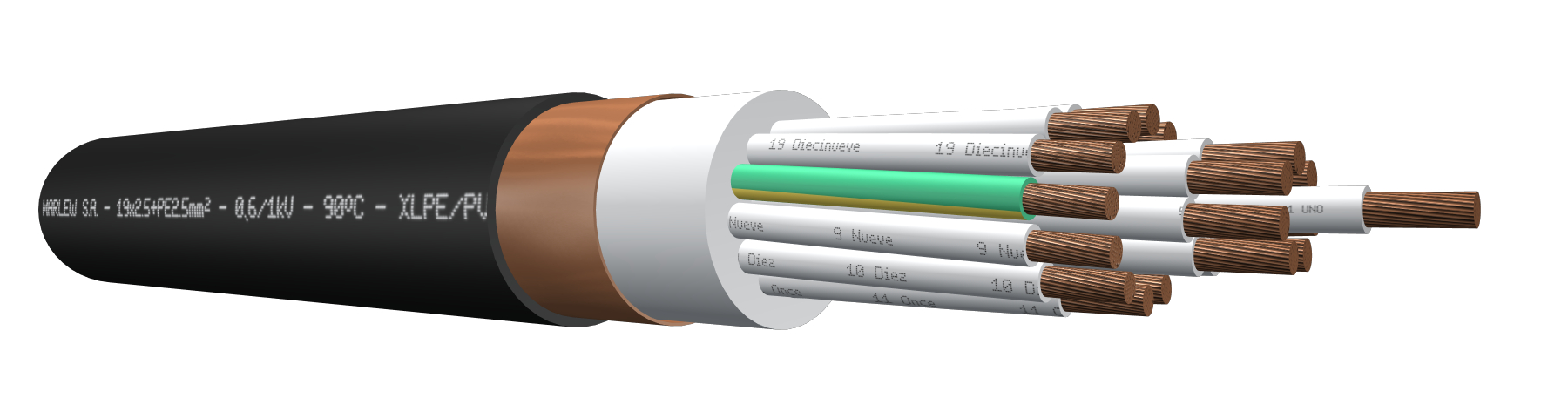
Copper tape shield
Control, signalling, protective equipment and electric controls for oil and gas industry (Midstream and Downstream) Installed in aerial trays, gutters or conduits, under roof or ladder under roof, buried in ducts or directly buried. It provides additional electromagnetic protection.
Features
Temperature ratings: 90°C (Operating) – 130°C (Overload) – 250°C (Short-Circuit)
Minimum temperature: Suitable for use in installations up to -30ºC
Voltage rating: 600/1000 Volt A.C. – 1200 Volt A.C. (Max) – 1500 Volt D.C.
Construction requirements: IEC 60502-1 – IRAM 2178-1
Conductor requirements: IRAM NM 280 – IEC 60228
Conductor: Annealed electrolytic copper - Flexible stranding class 5
Insulation: XLPE (Cross-Linked Polyethylene)
Shield: Helical copper tape with 100% coverage and adequate overlap
Sheath: Flame retardant PVC, enhanced hydrocarbons resistance, UV resistant and suitable for low temperature ratings, with low hydrochloric acid emissions (HCl)
Fire requirements: As per IEC 60332-3-24
Hydrocarbons resistance standard: UIC 895 OR (Oil and gas fuel)
Outdoors requirements: As per UL 2556 (UV Resistance)
Halogen emissions standard: IEC 60754-1 (HCl emission < 15%)
Electromagnetic interference protection

Fire-retardant

Flexible stranded conductors

Mineral oil resistant

UV resistant

Suitable for low temperatures
Identification
| Standard | ||
|---|---|---|
| Sheath | Conductors | |
| Multiconductor |  |  alphanumeric identification alphanumeric identification |
Instalation

DIMENSIONS & WEIGHT
| Cable Formation, N° Cond. x cross-section (mm²) | Diameter below shield mm | External diameter mm | Weight kg/km | Code |
|---|---|---|---|---|
| 5 x 1 | 9.1 | 12.5 | 224 | YC 0510 W |
| 7 x 1 | 9.9 | 13.3 | 250 | YC 0710 W |
| 10 x 1 | 11.8 | 15.1 | 312 | YC 1010 W |
| 12 x 1 | 12.7 | 16.0 | 349 | YC 1210 W |
| 14 x 1 | 13.5 | 16.8 | 386 | YC 1410 W |
| 19 x 1 | 15.4 | 18.7 | 472 | YC 1910 W |
| 24 x 1 | 17.0 | 20.4 | 556 | YC 2410 W |
| 30 x 1 | 18.8 | 22.1 | 652 | YC 3010 W |
| 37 x 1 | 20.7 | 24.1 | 777 | YC 3710 W |
| 48 x 1 | 23.3 | 26.7 | 946 | YC 4810 W |
| 3 x 1.5 | 9.0 | 12.4 | 223 | YC 0315 W |
| 4 x 1.5 | 9.0 | 12.4 | 227 | YC 0415 W |
| 5 x 1.5 | 9.8 | 13.2 | 252 | YC 0515 W |
| 7 x 1.5 | 10.7 | 14.0 | 295 | YC 0715 W |
| 10 x 1.5 | 12.7 | 16.0 | 369 | YC 1015 W |
| 12 x 1.5 | 13.7 | 17.0 | 416 | YC 1215 W |
| 14 x 1.5 | 14.6 | 18.0 | 462 | YC 1415 W |
| 19 x 1.5 | 16.7 | 20.0 | 573 | YC 1915 W |
| 24 x 1.5 | 18.5 | 21.8 | 680 | YC 2415 W |
| 30 x 1.5 | 20.5 | 23.9 | 820 | YC 3015 W |
| 37 x 1.5 | 22.5 | 25.9 | 965 | YC 3715 W |
| 48 x 1.5 | 25.3 | 28.7 | 1185 | YC 4815 W |
| 2 x 2.5 | 9.0 | 12.4 | 229 | YC 0225 W |
| 3 x 2.5 | 9.2 | 12.6 | 246 | YC 0325 W |
| 4 x 2.5 | 10.1 | 13.4 | 276 | YC 0425 W |
| 5 x 2.5 | 11.0 | 14.3 | 319 | YC 0525 W |
| 7 x 2.5 | 12.0 | 15.3 | 381 | YC 0725 W |
| 10 x 2.5 | 14.3 | 17.6 | 481 | YC 1025 W |
| 12 x 2.5 | 15.5 | 18.8 | 548 | YC 1225 W |
| 14 x 2.5 | 16.5 | 19.8 | 613 | YC 1425 W |
| 19 x 2.5 | 18.9 | 22.2 | 773 | YC 1925 W |
| 24 x 2.5 | 21.0 | 24.4 | 944 | YC 2425 W |
| 30 x 2.5 | 23.2 | 26.6 | 1127 | YC 3025 W |
| 37 x 2.5 | 25.6 | 29.0 | 1339 | YC 3725 W |
| 48 x 2.5 | 29.2 | 33.0 | 1726 | YC 4825 W |
| 2 x 4 | 9.7 | 13.1 | 263 | YC 0240 W |
| 3 x 4 | 10.4 | 13.7 | 303 | YC 0340 W |
| 4 x 4 | 11.4 | 14.7 | 355 | YC 0440 W |
| 5 x 4 | 12.4 | 15.8 | 416 | YC 0540 W |
| 7 x 4 | 13.6 | 16.9 | 505 | YC 0740 W |
| 10 x 4 | 16.2 | 19.5 | 643 | YC 1040 W |
| 12 x 4 | 17.6 | 20.9 | 740 | YC 1240 W |
| 14 x 4 | 18.8 | 22.1 | 835 | YC 1440 W |
| 19 x 4 | 21.5 | 24.9 | 1083 | YC 1940 W |
| 24 x 4 | 23.9 | 27.3 | 1312 | YC 2440 W |
| 30 x 4 | 26.5 | 30.1 | 1595 | YC 3040 W |
| 37 x 4 | 29.7 | 33.5 | 1957 | YC 3740 W |
ELECTRICAL CHARACTERISTICS
Resistances, reactance and intensity of admissible currents
| Nominal cross-section sq mm² | Electrical resistance at 20ºC in C.C Ohm/km | Electrical resistance at 90ºC in C.A. Ohm/km | Current-carrying capacity in free air. At 40°C as per IEC 364-5-523. Formations in perforated trays or ladder type. (Ampere) | ||||||
|---|---|---|---|---|---|---|---|---|---|
| 2x | 4x | 7x | 10x | 19x | 30x | 48x | |||
| 1 | 19.5 | 24.86 | -- | -- | -- | -- | -- | -- | -- |
| 1.5 | 13.3 | 16.96 | 23 | 20 | 16.1 | 11.5 | 11.5 | 10.4 | 8.1 |
| 2.5 | 7.98 | 10.18 | 31 | 28 | 21.7 | 15.5 | 15.5 | 14.0 | 10.9 |
| 4 | 4.95 | 6.31 | 43 | 36 | 30.1 | 21.5 | 21.5 | 19.4 | -- |
As from seven-conductors, we’ve additionally applied the correction factor for more than three conductors the chart 310.15 (B)(3)(a) of the NFPA70.